 LNEYA 산업용 냉각기 제조업체 공급 업체


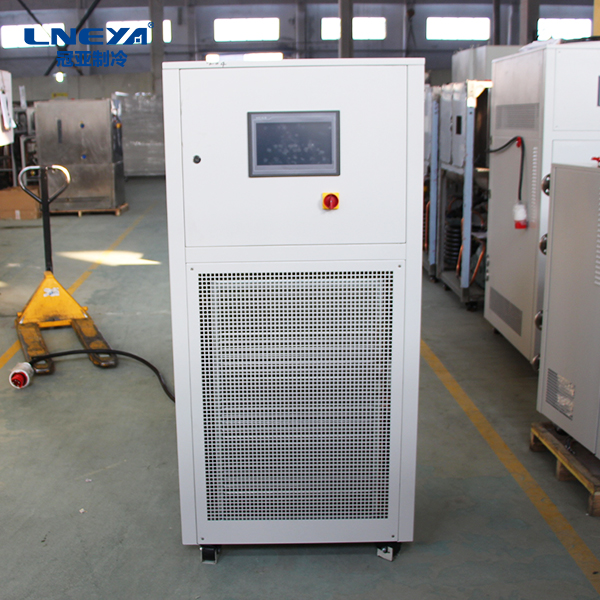
LNEYA microfluidic chip test solution
The microfluidic chip test is a program for testing the drive control chip. The LNEYA microfluidic chip test device specializes in processing various chip tests, and has certain advantages for the development of the chip environment.
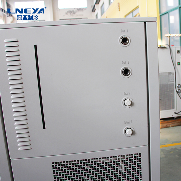
In order to improve the observability and controllability of each functional module, in order to verify the overall performance indicators of the chip to provide circuit structure support. The microfluidic chip test mainly consists of a screen, a driver chip, an FPC soft board, a power board, and an FPGA board. The screen and driver chip are based on practical applications, and have been soldered together during the test phase. With the screen, the driver and enable of the row and column can be visually displayed (excluding the dead pixels on the screen), and the Gamma correction for the chip, color scale The screen can be visually displayed, and the change process can be debugged online; then the screen and display control system are connected through the FPC soft board, and the screen voltage and control signal test points are reserved on the soft board; the power module realizes the display and the display on the screen. Voltage, and the total input of the driver chip power supply; the FPGA board is the control core of the entire test circuit, designing and storing some specific display effect images.
The circuit structure of the microfluidic chip test is based on the chip structure described above, and is designed with reference to its test requirements. The focus is on the power board and the FPGA board, and a power flow is provided for the entire test system to provide for each functional module. Adequate requirements for various thresholds, while preserving test points to monitor various AC and DC parameters of the driver chip. The other is to provide control and data flow of the test system, control the actions of each functional module, and independently create specific display data to verify the display effect of the driver chip.
The power supply of the microfluidic chip test system is divided into four parts: one part is the multi-channel power management VIN+5V required by the FPGA system, which is generated by the TPS5450. The second part drives the input voltage of the chip. After the LDO is stepped down, the core voltage and the 10 voltage VDDAB are generated. VDDI; three parts are the positive and negative high voltages required by AM-OLED. ELVDD and ELVSS are generated by TPS5450. The TPS5450 is characterized by different positive or negative voltages depending on the connection of the external inductor. In the fourth part, the voltage required for the level-shifting power supply is realized by the TPS65131. The power supply of the RGB row and column of the AM-OLED is adjustable from 4.6V to 6.5V, and a wide range of potentiometers can be used for flexible adjustment.
The microfluidic chip test interface is available in a variety of formats to facilitate conversion between multiple video data formats. The digital phase-locked loop is dynamically configurable to achieve clock multiplication, crossover, and phase locking, providing sufficient clock resources for the entire test system. In addition, the FPGA has a JTAG in-circuit debugging interface, which provides convenience for the configuration of the AM-OLED driver control chip register, and supports a variety of display formats and conversion functions, and provides sufficient resources for the verification of the functions of the AM-OLED drive control chip.
Microfluidic chip test as a complex control system, can also achieve the collaborative work of different modules through FPGA, can fully meet the various functional requirements of the test chip.
LNEYA microfluidic chip test mainly uses the refrigeration heating temperature control technology to conduct temperature control tests on test items and integrated circuits to meet the needs of various tests.
(참고: 일부 콘텐츠는 관련 논문에서 발췌한 것입니다. 저작권을 침해하는 경우 제때 삭제해 주시기 바랍니다.)
관련 권장 사항
-
증류로 용매 회수 온도를 제어하는 방법은 무엇입니까?
11081. If the product quality is not affected by the presence of air at a higher temperature, it can be recovered at normal pressure first, and when the temperature exceeds the normal pressure boiling point of the desolvent by 10 degrees, when the so...
세부 정보 보기 -
히터에 역류를 추가하면 겨울철에도 언제 어디서나 온수가 나옵니다.
1012The principle is also simple. A water pipe is added at the outlet of the hot water pipe to form a closed circuit. The recirculation pump is connected to the water heater. When the tap is turned on, the circulating pump automatically pumps the col...
세부 정보 보기 -

Maintenance instructions for compressors at minus 85 degrees ultra low temperature freezer
1100The compressor in the ultra-low temperature freezer of minus 85 degrees is one of the main components, and its performance is very important, so maintenance is also very important. For manufacturers of sub-85 degree ultra-low temperature freezer c...
세부 정보 보기 -
대형 냉장 및 가열 서큘레이터와 테스트 챔버의 차이점
9461. 특수한 상황에서 고온 테스트의 경우 고온 및 저온 테스트 챔버가 요구 사항을 충족하지 못할 수 있습니다. 일반적으로 고온 및 저온 테스트 상자의 고온 상한은 200 ℃이며 그 ...
세부 정보 보기


